
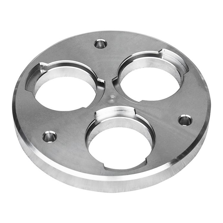
In modern pipeline construction systems, standard ANSI DIN flange solutions play a critical role in creating
reliable, maintainable, and pressure-resistant connections. These flange standards are widely used across oil and gas,
petrochemical, water treatment, power generation, shipbuilding, HVAC, and industrial process piping. For engineers,
contractors, procurement teams, and plant designers, understanding the differences between ANSI and DIN flange standards
is essential for selecting the right components, maintaining system compatibility, and ensuring safe long-term operation.
This guide provides a clear and SEO-friendly overview of ANSI flanges and DIN flanges for pipeline
construction systems, including definitions, applications, advantages, material options, pressure ratings, dimensional
considerations, and standard comparison tables. The content is designed for direct use in blog posts, category pages,
product education pages, and industry resource pages.
A standard ANSI DIN flange refers to a flange manufactured in accordance with either the American National
Standards Institute (ANSI) piping standards or the German/European DIN standards. These standards define flange
dimensions, bolt hole patterns, pressure ratings, facing types, and mechanical compatibility for use in piping systems.
In pipeline construction systems, flanges are used to connect pipes, valves, pumps, filters, pressure vessels, and other
equipment. Unlike welded joints, flanged joints allow for easier assembly, disassembly, inspection, maintenance, and
replacement. This is one reason why ANSI and DIN flanges remain among the most widely specified connection methods in
industrial piping.
The term ANSI flange is commonly used in North America and international projects that follow ASME/ANSI
dimensional conventions. The term DIN flange is associated with German industrial standards and is widely used
in Europe and many global engineering systems. Although they serve similar functions, ANSI and DIN flanges differ in
dimensions, pressure classes, and bolt patterns, which means they should not be mixed without proper engineering review.
Flanges are one of the most important connection elements in pipeline construction. They enable secure and controlled
joining of pipeline components while allowing future access for maintenance or modification. In large-scale pipeline
construction systems, flange selection affects pressure integrity, leak prevention, installation speed, maintenance cost,
and overall system reliability.
Key reasons why flanges are widely used in piping systems include:
ANSI flanges are typically referenced through ASME standards such as ASME B16.5 for pipe flanges and flanged
fittings. In practice, the term “ANSI flange” is often used to describe flanges made to these dimensional and pressure
class standards. ANSI-style flanges are common in the United States and in export projects where ASME compatibility is
required.
ANSI flange pressure classes are usually expressed as:
These pressure classes indicate the pressure-temperature capability of the flange, depending on material type and
operating temperature. In pipeline construction systems, Class 150 and Class 300 are among the most common specifications
for general industrial service, while higher classes are used for more demanding high-pressure applications.
DIN flanges are based on German industrial standards and are widely used in Europe and international systems. DIN flange
specifications define the flange dimensions, bolt circle diameter, bolt size, facing type, and pressure designation.
Common DIN pressure ratings are based on nominal pressure, often represented as:
The “PN” value stands for nominal pressure, although actual working pressure depends on material, temperature, and design
conditions. DIN flanges are frequently used in water systems, chemical lines, mechanical equipment, HVAC piping, and
process industries requiring metric-based engineering standards.
Although ANSI and DIN flanges perform the same basic function, they are not dimensionally identical. This means a direct
connection between the two standards is generally not possible without a properly designed adapter or matching flange set.
Below is a practical comparison of ANSI and DIN flange characteristics.
| Feature | ANSI Flange | DIN Flange |
|---|---|---|
| Primary Standard Region | North America, ASME-based global projects | Europe, metric-based international projects |
| Common Pressure Designation | Class 150, 300, 600, 900, etc. | PN 6, PN 10, PN 16, PN 25, etc. |
| Dimensional System | Imperial / inch-based | Metric-based |
| Bolt Pattern | ASME-defined bolt circle and hole count | DIN-defined bolt circle and hole count |
| Interchangeability | Matches ANSI/ASME dimensions | Matches DIN dimensions |
| Common Applications | Oil & gas, petrochemical, power, industrial piping | Water treatment, HVAC, chemical plants, industrial piping |
| Typical Markets | U.S., Canada, Middle East, global EPC projects | Germany, EU, international metric systems |
Standard ANSI DIN flange products are available in multiple design types depending on connection method, pressure
requirement, and installation conditions. The most common flange styles used in pipeline construction systems include:
A weld neck flange features a long tapered hub that is welded to the pipe. This design provides excellent stress
distribution, strength, and fatigue resistance, making it suitable for high-pressure and high-temperature services.
A slip-on flange slides over the pipe and is then welded in place. It is easier to align and install, making it a common
choice for lower-pressure applications and general industrial piping.
A blind flange closes the end of a pipe, valve, or vessel opening. It is used for pressure testing, future expansion, or
temporary isolation of pipeline sections.
Socket weld flanges are inserted into the pipe socket and welded around the outside. They are commonly used in smaller
diameter piping systems where leak resistance and compact design are important.
A threaded flange has internal threads and can be installed without welding. It is useful in low-pressure systems or
locations where welding is impractical.
Lap joint flanges are used with a stub end and are ideal for systems that require frequent dismantling or where alignment
is difficult. They are often chosen for stainless steel and corrosion-resistant piping systems.
The flange face is one of the most important features affecting sealing performance. The face style determines how the
gasket sits and how the load is distributed during bolting. Common flange faces include:
| Face Type | Description | Typical Use |
|---|---|---|
| Raised Face (RF) | Raised sealing surface surrounding the bore | General industrial piping and pressure systems |
| Flat Face (FF) | Entire face is flat for full-face gasket contact | Cast iron equipment and low-pressure systems |
| Ring Type Joint (RTJ) | Grooved face for metal ring gasket sealing | High-pressure and critical service lines |
| Tongue and Groove | Matching male/female sealing surfaces | Specialized sealing applications |
| Male and Female | Interlocking face profile for improved alignment | Precision piping assemblies |
Flange material selection depends on pressure, temperature, corrosion resistance, weldability, and industry requirements.
Standard ANSI DIN flange products are manufactured in a wide range of materials to suit different pipeline construction
systems.
| Material | Common Characteristics | Typical Application |
|---|---|---|
| Carbon Steel | Cost-effective, strong, widely available | Water, oil, gas, general industrial pipelines |
| Stainless Steel | Corrosion-resistant, durable, hygienic | Chemical, food, pharmaceutical, marine systems |
| Alloy Steel | High strength, temperature resistance | Power plants, refinery, high-temperature service |
| Duplex Stainless Steel | Excellent corrosion and pitting resistance | Offshore, seawater, aggressive chemical media |
| Nickel Alloys | Superior resistance in extreme environments | Specialized chemical and corrosive systems |
Correct pressure rating and size selection are essential for a safe and efficient pipeline construction system. Choosing
the right standard ANSI DIN flange requires checking the pipeline nominal diameter, pressure class or PN rating, temperature
range, gasket type, bolt specification, and fluid characteristics.
Important selection factors include:
Standard flanges are preferred in pipeline construction because they provide repeatable performance and simplified
maintenance. The advantages of ANSI and DIN flange systems include:
| Advantage | Explanation |
|---|---|
| Standardization | Uniform dimensions help engineers design and replace components efficiently. |
| Maintenance Access | Flanged joints can be opened for inspection, cleaning, and repair. |
| Leak Control | Properly designed flanged joints provide strong sealing performance. |
| Wide Availability | ANSI and DIN flange sizes are widely used and broadly specified worldwide. |
| System Flexibility | Flanged joints simplify equipment replacement and process upgrades. |
| High Pressure Capability | Many flange classes are designed for demanding industrial operating conditions. |
Although standard ANSI DIN flange systems offer many benefits, there are also challenges that must be addressed during
project planning and installation. One of the most common issues is standard mismatch. A flange made to ANSI dimensions
usually cannot connect directly to a DIN flange due to differences in bolt circles, thickness, face dimensions, and bore
alignment.
Other common challenges include:
Standard ANSI DIN flange systems are used in a broad range of industrial applications. Their versatility and standardized
design make them suitable for both new construction and maintenance projects.
| Industry | Typical Use of Flanges |
|---|---|
| Oil and Gas | Pipeline joints, process equipment, pressure containment systems |
| Petrochemical | Refinery lines, chemical transport, high-temperature process piping |
| Water Treatment | Pump connections, valves, filtration systems, distribution piping |
| Power Generation | Steam lines, cooling systems, boiler auxiliaries, turbine support piping |
| HVAC | Chilled water, heating lines, mechanical equipment connections |
| Shipbuilding | Marine piping, ballast systems, fuel lines, onboard utilities |
| Food and Beverage | Hygienic process piping and clean service connections |
| Pharmaceutical | Sanitary transfer systems, sterile process lines |
Choosing the correct flange for pipeline construction systems requires a structured engineering approach. The following
checklist can help guide specification and procurement decisions:
A flange joint is only as effective as its gasket and bolting system. Even a well-designed standard ANSI DIN flange can leak
if the gasket material, bolt size, or tightening sequence is incorrect. Gaskets must be selected based on fluid type,
temperature, pressure, and flange face design.
Common gasket types include non-asbestos sheet gaskets, spiral wound gaskets, ring gaskets, PTFE gaskets, and rubber
gaskets for lower-pressure systems. Bolt materials are typically chosen for strength and corrosion resistance and may
include carbon steel, alloy steel, or stainless steel depending on the service conditions.
In global pipeline construction systems, dimensional compatibility is a frequent concern. ANSI and DIN flanges may appear
similar in size, but differences in bolt count, bolt circle diameter, flange thickness, and sealing face geometry can
prevent direct interchangeability.
Engineering teams should never assume that a nominal size in ANSI is identical to the same nominal size in DIN. Instead,
every flange should be checked against the relevant standard drawing and dimensional table. For mixed-standard projects,
purpose-designed transition pieces or adapter flanges may be required.
Proper installation is essential for long service life and leak-free performance. Best practices for standard ANSI DIN
flange installation include:
The following keyword phrases are commonly searched by engineers, buyers, and technical readers looking for flange
information in pipeline construction systems:
Below is a simplified reference table showing common nominal sizes used in industrial piping. Actual dimensions vary by
standard, pressure class, and specification, so final engineering verification is always required.
| Nominal Size | Metric Equivalent | Common Use |
|---|---|---|
| 1/2 inch | DN 15 | Instrumentation, small utility piping |
| 3/4 inch | DN 20 | Utility service, small process lines |
| 1 inch | DN 25 | General industrial piping |
| 2 inch | DN 50 | Process lines, valves, equipment connections |
| 4 inch | DN 100 | Water, chemical, and utility systems |
| 6 inch | DN 150 | Industrial pipelines and equipment interfaces |
| 8 inch | DN 200 | Large process lines and pipeline runs |
| 12 inch | DN 300 | High-capacity pipeline construction |
The standard ANSI DIN flange remains an essential component in pipeline construction systems because of its
reliability, standardization, and adaptability across industries. Whether a project follows ANSI/ASME conventions or DIN
metric standards, the right flange selection supports safe operation, efficient maintenance, and long-term sealing
performance.
For successful pipeline design and installation, engineers must evaluate flange type, pressure class, material grade,
face style, gasket selection, and dimensional compatibility. When specified correctly, ANSI and DIN flanges help build
durable piping networks that meet demanding industrial requirements.
If you need a foundational industry page, product category introduction, or technical blog section on standard ANSI DIN
flange for pipeline construction systems, the content above is structured for SEO performance, clarity, and direct HTML
integration.
```


Urheberrecht © 2022 Zhejiang Songlin Flange Co., Ltd.
SitemapDiese Website verwendet Cookies, um sicherzustellen, dass Sie das beste Erlebnis auf unserer Website erhalten.

 English
 Español
 Pусский
 Français
 日本語
日本語 한국어
한국어 العربية
 Italiano
 Nederlands


 WhatsApp
 Telefon
Kommentar
(0)